How to Choose Temperature Measurement Sensors?
Choosing the right temperature measurement sensors is more than comparing price, range, and packaging. It is a reliability decision made around a real process. A probe near a furnace sees radiant heat, vibration, and rapid thermal changes. A sensor inside a pharmaceutical refrigerator faces different risks, including condensation, calibration drift, and contamination. The best choice begins with the measurement environment, not the product catalogue.
Market data shows why this decision deserves closer attention. MarketsandMarkets estimates that the global temperature sensor market could grow from about USD 7.5 billion in 2023 to USD 11.5 billion by 2028. Its analysis highlights rising demand across industrial automation, automotive systems, healthcare, and consumer electronics. These figures indicate strong adoption, but they do not identify the right sensor for every application. That part requires engineering judgment. NIST guidance also stresses traceability, uncertainty evaluation, and calibrated reference equipment. A precise display is not enough.
This guide examines thermocouples, resistance temperature detectors, thermistors, and infrared sensors. It compares accuracy, response time, operating range, installation method, signal conditioning, and maintenance needs. IEC 60751 provides important requirements for industrial platinum RTDs, while ISO/IEC 17025 supports confidence in calibration laboratories. Still, standards cannot replace field testing. A sensor may perform well in a laboratory and fail beside a steam line. Small details matter. Cable routing, probe placement, shielding, and calibration intervals can change the result. No selection method is perfect, and this guide cannot remove every uncertainty. It can, however, help engineers ask better questions before purchasing equipment.
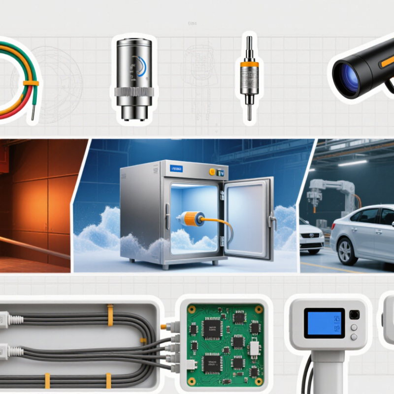
Temperature Measurement Basics and Sensor Operating Principles
Choosing a temperature sensor starts with its operating principle, not its housing or connector. Sensors convert heat into a measurable electrical signal.
Resistance temperature detectors measure resistance changes in a metal element. IEC 60751 lists Class A tolerance as ±(0.15 + 0.002|t|)°C. At 100°C, that equals ±0.35°C. This suits laboratory work and stable industrial processes, but response can be slower.
Thermocouples generate voltage through the Seebeck effect. Their output is small, often measured in millivolts, so cable quality and reference-junction compensation matter. IEC 60584-1 specifies Type K Class 1 tolerance as ±1.5°C or ±0.004|t|, whichever is larger, across defined temperature ranges. They tolerate vibration well. Accuracy varies with installation.
Thermistors change resistance sharply over a narrow range. They respond quickly, but their readings are strongly nonlinear. The uncertainty guide in NIST Technical Note 1297 stresses that calibration results must include measurement uncertainty, not only the displayed value. A sensor can be accurate on paper and wrong at the process point. That happens.
Mounting depth, airflow, thermal contact, and insulation can matter more than the sensing element. A poorly seated probe may measure the pipe surface instead of the fluid. I have seen that error survive a clean calibration certificate. Check the actual temperature range, response time, chemical exposure, vibration, and wiring distance before choosing. Sensor selection is partly engineering, partly disciplined skepticism.
How to Choose Temperature Measurement Sensors?
Sensor selection depends on the required temperature range, accuracy, response time, stability, and installation environment.
This chart compares representative operating ranges for common sensor technologies. Thermocouples are suitable for wide and high-temperature measurements,
RTDs provide stable and accurate readings over a broad range, while thermistors are generally used for narrower ranges and high sensitivity.
Compare Sensor Types, Accuracy, Range, and Response Time
How to Choose Temperature Measurement Sensors?
Compare Sensor Types, Accuracy, Range, and Response Time
When choosing a temperature sensor, start with the process, not the catalog. A resistance sensor often provides stable, precise readings for moderate industrial temperatures. Thermocouples usually cover wider ranges and tolerate vibration, but their accuracy can depend on wiring and reference compensation. Thermistors respond quickly and work well in compact equipment, although their useful range is narrower.
Accuracy needs a practical definition. A sensor listed with ±0.5°C accuracy may still produce poor results if installation adds heat conduction errors. Check the complete measurement chain, including the transmitter, cable, and display. In a calibration test, place the probe beside a trusted reference, not several centimeters away. Small distances matter. Also inspect drift over time, especially near heaters, motors, or chemical exposure. Specifications can look impressive.
Range and response time must match the real event. A slow, protected probe may survive a furnace wall but miss a rapid temperature spike. A thin probe can react in seconds, yet it may be easier to damage. Consider airflow, immersion depth, mounting pressure, and cleaning cycles. I have seen a highly accurate sensor fail because its tip touched a metal fitting. That was not a sensor fault alone. It exposed a weak installation decision. Record the expected minimum, maximum, rate of change, and acceptable error before selecting the sensor.
Select the Most Suitable Temperature Sensor for Your Application
Choosing a temperature sensor starts with the application, not the catalogue. Measure the actual range, accuracy, response time, and installation space. A food-processing tank may need a cleanable probe, while an engine test requires fast response and strong vibration resistance. Ambient moisture, pressure, chemicals, and electrical noise also affect sensor performance.
In field work, I have seen accurate sensors produce unreliable readings because their cables were poorly routed. Placement matters as much as sensor type. Contact sensors suit many solid surfaces, but they need firm contact and suitable thermal coupling. Non-contact sensors are useful for moving or delicate targets, yet surface emissivity can distort results. Check calibration records, connection requirements, maintenance access, and the expected service life before purchasing. A neat specification sheet can still mislead.
Tips: Define the measurement point clearly. Compare the sensor range with real operating conditions, not ideal ones. Leave a safety margin. Test a sample during normal operation when possible. Watch for slow response, unstable readings, or difficult cleaning. These details often reveal problems that laboratory checks miss. Avoid choosing the cheapest option automatically; replacement labor may cost more than the sensor. Still, an expensive sensor is not always better. I have sometimes over-specified equipment, then discovered that a simpler design was easier to maintain and sufficiently accurate. The final choice should reflect evidence from the process, installation limits, and verification results.