Selecting the right flow sensors can determine whether an industrial process runs smoothly or produces costly measurement errors. In chemical plants, water facilities, food factories, and energy systems, flow data guides dosing, batching, cooling, and safety decisions. A sensor mounted on a stainless-steel pipe may face vibration, pressure changes, abrasive particles, or sudden temperature shifts. The best choice depends on the fluid, pipe size, required accuracy, and installation conditions. There is no universal winner.
This guide examines leading flow sensors for industrial use, including electromagnetic, ultrasonic, Coriolis, vortex, turbine, and differential-pressure technologies. Each type offers practical strengths and clear limitations. Electromagnetic models suit conductive liquids and have no moving parts. Coriolis meters provide excellent mass-flow accuracy but often cost more. Ultrasonic sensors can measure flow without cutting the pipe, although air bubbles may weaken their readings. Small details matter. A poorly positioned sensor can undermine an otherwise advanced system.
Reliable selection requires more than comparing product brochures. Engineers should review calibration records, pressure ratings, material compatibility, signal output, maintenance access, and compliance documentation. Field experience also matters because laboratory performance may differ from results inside a crowded plant room. Even experienced teams make assumptions that later need correction. That is worth acknowledging. A dependable flow sensor should deliver stable readings, support verification, and match the process over time. The sections ahead compare these technologies by accuracy, operating cost, durability, installation demands, and typical industrial applications, helping readers make a more defensible purchasing decision.
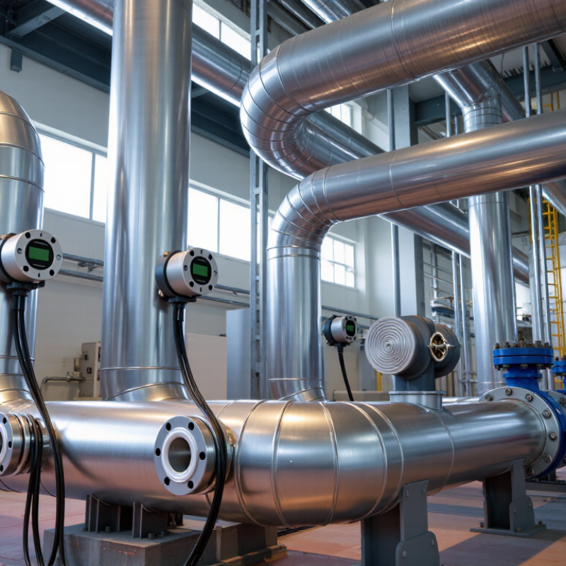
Industrial flow measurement turns moving fluid into a usable operating signal. It supports batching, custody checks, pump protection, and energy control. The principle matters. Electromagnetic meters sense conductive liquid velocity. Coriolis devices measure mass flow through vibrating tubes. Ultrasonic meters estimate velocity from sound travel time. Vortex meters detect repeating swirls behind a bluff body.
Selection begins with the process, not the catalog. Record fluid density, viscosity, conductivity, temperature, pressure, pipe size, and expected flow range. A turbine sensor can respond well to clean, stable liquids, but particles may damage its moving parts. Differential-pressure devices tolerate many installations, yet they create permanent pressure loss. Thermal mass sensors suit gases, although humidity and changing composition can distort readings. Accuracy claims mean little without the actual range.
Installation often decides whether a good instrument performs badly. Keep required straight-pipe lengths, remove air pockets, and prevent vibration near the sensing point. Calibration should use a traceable reference and match real operating conditions. In practice, maintenance teams sometimes trust a dashboard value too quickly. That is risky. A clogged impulse line or empty pipe can produce a convincing number. Field work often reveals overlooked details, including cleaning access, cable routing, and future process changes. The better question is not “Which sensor is best?” It is “Which principle remains dependable here?”

Industrial flow sensors measure movement differently, so their performance depends on the fluid, pipe, and installation conditions. Differential pressure sensors compare pressure before and after an orifice or venturi section. The pressure difference indicates flow velocity. They suit many gases and liquids, but restricted openings can create permanent pressure loss.
Magnetic flow sensors generate a magnetic field across a conductive liquid. As the liquid moves, it produces a voltage related to velocity. They have no internal moving parts, which helps with dirty wastewater and corrosive process liquids. However, the pipe must remain full, and the liquid needs enough electrical conductivity. Poor grounding can produce unstable readings. Small details matter.
Ultrasonic sensors send sound waves through the pipe and calculate flow from transit-time changes. They can measure without cutting the pipe, although air bubbles, deposits, and weak acoustic contact may reduce accuracy. Coriolis sensors detect twisting forces caused by moving mass, providing direct mass-flow measurement and useful density data. They are highly precise but often cost more and require careful support.
Vortex sensors measure repeating swirls behind a bluff body. Their signal can weaken at low flow rates or during strong vibration. Turbine sensors use rotating blades, making them responsive but more vulnerable to wear and contamination. In field commissioning, technicians should check straight pipe lengths, calibration records, grounding, and actual operating temperatures. A selected sensor may look correct on paper, yet perform poorly beside a pump. More testing is often needed.
How major industrial flow sensor types work and their representative typical accuracy
The chart shows representative typical accuracy values expressed as a percentage of full-scale flow. Lower values indicate better nominal accuracy. Actual performance depends on fluid properties, installation conditions, pipe size, calibration, and operating range.
For industrial service, the strongest flow sensor depends on the fluid, not popularity. Coriolis meters often deliver 0.1–0.2% mass-flow accuracy. They suit dense liquids, slurries, and custody-transfer duties. Magnetic meters commonly reach about ±0.5% accuracy, but only with conductive liquids. Ultrasonic meters can approach ±0.5–1% accuracy in clean, full pipes. Differential-pressure meters remain useful across wide sizes, although typical accuracy is closer to 1–2%. These ranges reflect values reported in technical reviews and application data, not guaranteed site performance. The U.S. Department of Energy’s 2022 Industrial Decarbonization Roadmap links better process measurement with energy-efficiency opportunities. Small errors scale quickly in large plants.
Range matters as much as accuracy. A sensor rated for 10–1,000 L/min may become unstable near its lower limit. Check turndown, pressure, temperature, viscosity, and gas content together. ISO 5167 and ISO 5168 emphasize installation conditions and uncertainty evaluation. Reality is less tidy. Pumps vibrate, pipes collect residue, and operators sometimes measure too close to elbows.
Material selection protects reliability. Stainless steel suits many water and chemical services, while PTFE liners handle aggressive liquids. Highly corrosive fluids may need special alloys, but compatibility charts deserve a real process review. Installation can decide the result. Magnetic meters need grounding and a full pipe. Ultrasonic meters need a developed flow profile, often requiring straight pipe upstream. For natural-gas measurement, AGA Report No. 9 addresses ultrasonic-meter performance and installation. Leave room for calibration access. You may regret skipping it.
| Flow Sensor Type | Best-Suited Fluids | Typical Accuracy | Typical Turndown Ratio | Typical Flow Range | Common Wetted Materials | Pressure Loss | Installation Requirements | Key Limitations | Typical Industrial Applications |
|---|---|---|---|---|---|---|---|---|---|
| Electromagnetic | Conductive liquids, including water, wastewater, slurries, acids, and process chemicals | ±0.2% to ±0.5% of reading | Typically 20:1 to 100:1 | Approximately 0.1 to 10 m/s velocity; line sizes from about 15 mm to more than 2,000 mm | Rubber, PTFE, PFA, ceramic liners; electrodes commonly stainless steel, Hastelloy-type alloys, or tantalum | Very low; no obstruction in the flow tube | Pipe must remain full; grounding is required; straight-run requirements are commonly about 5D upstream and 2D downstream, depending on design | Cannot measure non-conductive liquids such as most hydrocarbons; electrodes must remain wetted | Water treatment, chemical processing, pulp and paper, mining, food and beverage liquids |
| Ultrasonic Transit-Time | Clean liquids and some moderately clean gases; suitable for many non-conductive fluids | ±0.5% to ±1.0% of reading for well-installed liquid meters; higher uncertainty is possible in gases or difficult piping | Typically 20:1 to 100:1 | Approximately 0.01 to 12 m/s, depending on pipe size, fluid, and transducer arrangement | External clamp-on sensors may have stainless steel or polymer housings; wetted pipe materials remain unchanged | Negligible for clamp-on designs | Requires suitable acoustic coupling and adequate straight pipe; clamp-on units need clean, accessible pipe surfaces and correct sensor spacing | Performance decreases with bubbles, heavy solids, deposits, poor acoustic coupling, or highly disturbed flow | Temporary surveys, utility monitoring, chilled-water systems, large-pipe measurement, non-invasive process checks |
| Coriolis Mass | Liquids, gases, slurries, viscous products, and fluids requiring direct mass measurement | ±0.1% to ±0.2% of reading for many liquid applications; gas accuracy is commonly lower | Typically 20:1 to 100:1 | From a few grams per minute to several hundred tonnes per hour, depending on tube size and design | Stainless steel, nickel alloys, and specialized alloys; seals may be elastomeric or PTFE-based | Moderate to high, especially with small-bore tubes, viscous fluids, or high flow rates | Requires full support and correct alignment; avoid excessive vibration; some installations need flow conditioning or pulsation control | Higher purchase cost, greater weight, possible zero drift, and limited practicality for very large line sizes | Batching, custody-related process control, fuel measurement, dosing, blending, and high-value liquids |
| Vortex | Steam, gases, air, and clean or moderately clean low-viscosity liquids | ±0.7% to ±1.5% of reading for liquids; commonly ±1% to ±2% for gases and steam | Typically 10:1 to 30:1 | Approximately 0.3 to 80 m/s, depending on fluid phase, density, pressure, and meter size | Stainless steel or alloy body; sensing components commonly stainless steel or hardened alloys | Moderate; an internal bluff body creates a permanent pressure drop | Requires a full pipe and stable velocity profile; typical straight-run guidance is about 10D upstream and 5D downstream, subject to meter design | Sensitive to vibration, pulsating flow, low-density gas, entrained solids, and operation below the minimum Reynolds number | Boiler steam, compressed air, natural gas, utility gases, and process-water monitoring |
| Thermal Mass | Clean, dry gases and air; some models support selected mixed or wet-gas services | ±1% to ±2% of reading plus a small percentage of full scale, depending on calibration and gas composition | Typically 50:1 to 100:1; some designs offer wider ranges | Gas velocities commonly from about 0.1 to 100 m/s, depending on probe and pipe size | Stainless steel probe and sensor; protective coatings or specialty alloys may be available | Very low for insertion types; low to moderate for inline designs | Insertion depth and orientation must be controlled; straight-run requirements often range from 10D to 30D upstream, depending on disturbances | Accuracy depends strongly on gas composition, pressure, temperature, humidity, and sensor cleanliness | Compressed-air audits, combustion-air monitoring, nitrogen distribution, ventilation, and gas leak detection |
| Variable Area | Clean liquids and gases with relatively stable density and viscosity | Approximately ±1.5% to ±5% of full scale, depending on scale, float, and transmitter configuration | Typically 4:1 to 10:1 | From a few millilitres per minute to several hundred cubic metres per hour | Glass, acrylic, stainless steel, brass, PTFE, and other chemically compatible materials | Low to moderate, depending on float design and flow rate | Must be installed in the specified orientation, usually vertically with upward flow; requires density and viscosity compensation for accurate readings | Limited accuracy and rangeability; readings are affected by fluid properties, vibration, and installation angle | Panel flow indication, purge systems, laboratory utilities, cooling-water circuits, and low-cost local monitoring |
| Positive Displacement | Clean to moderately clean liquids, including viscous oils, fuels, and chemical products | ±0.1% to ±0.5% of reading after calibration | Typically 10:1 to 100:1 | From very low liquid flow rates to several hundred cubic metres per hour, depending on displacement element and size | Stainless steel, carbon steel, aluminum, bronze, PTFE, PEEK, and compatible elastomers | Moderate to high; increases with viscosity, contamination, and flow rate | Requires filtration where particles may damage the measuring element; piping must prevent excessive pulsation and mechanical stress | Moving parts can wear or jam; unsuitable for abrasive solids, entrained gas, or dirty fluids without adequate protection | Fuel dispensing, lubricant measurement, chemical batching, hydraulic oil, and high-viscosity product transfer |
Note: Performance figures are representative industrial ranges rather than guaranteed specifications. Actual accuracy, flow range, pressure loss, material compatibility, and straight-run requirements depend on the meter size, calibration, fluid properties, pressure, temperature, piping configuration, and installation conditions.
Selecting a flow sensor depends on the medium, pipe design, pressure, temperature, and required accuracy. For conductive liquids, electromagnetic sensors work well because they have no internal moving parts. They suit water treatment, chemical processing, and slurry lines. Coriolis sensors measure mass flow and density together. This makes them valuable for dosing, food processing, and high-value liquids. They are highly accurate, but installation cost and pipe support requirements can be significant.
For steam and clean gas systems, vortex sensors offer stable readings across many industrial conditions. Thermal mass sensors are useful for compressed air and other clean gases, especially when direct mass measurement matters. Ultrasonic clamp-on sensors provide non-invasive measurement. They reduce shutdown time and protect older pipes from cutting or welding work. Turbine sensors can perform well with clean, low-viscosity liquids, although contaminated fluids may wear their internal parts quickly.
Application details matter more than impressive specifications. A sensor rated for high accuracy may still fail when bubbles, vibration, or poor grounding affect the line. That happens often. Engineers should check straight-pipe requirements, calibration records, signal compatibility, and cleaning procedures before approval. In field work, the easiest sensor to install is not always the easiest to maintain. A careful trial on the actual process can reveal problems that a datasheet hides.
Choosing the right flow sensor requires more than comparing accuracy figures. Magnetic meters suit conductive liquids, while Coriolis meters measure mass flow and density directly. Ultrasonic meters offer low-pressure-drop measurement without cutting the pipe. Vortex meters work well with clean steam and gases. Thermal-mass sensors support compressed-air monitoring. Fit matters.
The International Energy Agency’s Energy Efficiency 2023 report estimates that industry consumed about 37% of global final energy in 2022. Small measurement errors can therefore influence significant operating costs.
Maintenance begins with installation quality.
Technicians should inspect electrodes, impulse lines, seals, grounding, and cable connections during scheduled shutdowns. On a real production line, blocked strainers and air bubbles often create unstable readings. Cleaning alone may not solve the problem.
The U.S. Department of Energy reports that compressed-air leaks can waste 20–30% of system output. That figure is sobering, although site conditions make the actual loss uncertain. A leak survey and verified flow reading should be compared before replacing a sensor.
Calibration intervals should reflect process risk, vibration, temperature, fluid chemistry, and historical drift.
ISO/IEC 17025 recommends competent laboratories and traceable measurement results. NIST Technical Note 1297 also stresses documenting measurement uncertainty, not just displaying a single accuracy number. Keep certificates, zero checks, loop tests, and as-found readings together.
Trend data often reveals deterioration earlier than an alarm. Extending intervals may reduce maintenance costs, but it can also hide gradual drift. That trade-off deserves regular review.
As a specialist in environmental and flow sensor technology, ScioSense enables companies to use the planet’s resources more sustainably, helping to create a healthier future for all.